ArduPilot — Telemetry Radio Setup Guide
All instructions below assume the MicoAir radio's factory default settings: 57600 baud, duplex mode, automatic pairing on power-up (LED solid green).
Mission Planner GCS — official download
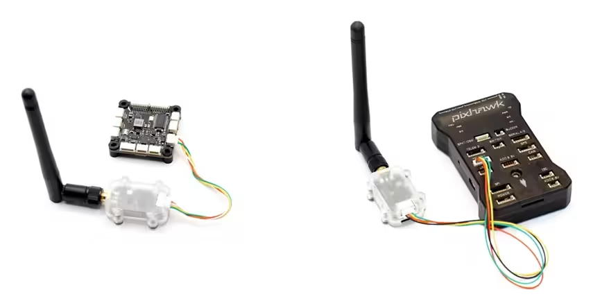
Step 1 — Connect the radio to the flight controller
Connect the MicoAir radio to the telemetry port on your ArduPilot flight controller — usually TELEM1 / SERIAL1, though any free serial port also works (every serial port on an ArduPilot flight controller is fully configurable). Note: the radio's Rx connects to the flight controller's Tx, and Tx to Rx.
On a Pixhawk 2.4.8 or Pixhawk 6, you can connect directly using the cable supplied with the radio.
The LR900 series and LR24 series radios have different connector pinouts. Check the correct one against the matching manual:
- LR900 Telemetry Radio — User Manual
- LR24 Telemetry Radio — User Manual (coming soon)
Step 2 — Configure the flight controller
Connect the flight controller to your computer via USB, open Mission Planner, and connect to the flight controller.
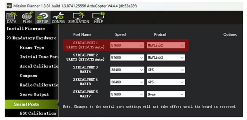
With the radio on the TELEM1 / Serial1 port, configure the flight controller's Serial1 parameters. In the full parameter tree, find the SERIAL1 parameters and set:
SERIAL1_BAUD = 57(57600)SERIAL1_PROTOCOL = 2(MAVLink2)
The latest Mission Planner (1.3.81) also lets you set port parameters directly on the SETUP → Serial Ports page.
Step 3 — Connect the other radio to the computer
Connect the second radio to your computer with a Type-C cable. Note: in their default mode, the LR900 and LR24 do not require you to distinguish an "air" end from a "ground" end.
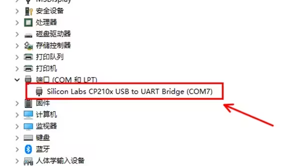
The first time you use it, install the driver. For the CP2102 driver on Windows, see:
CP2102 Driver Installation Guide (Windows)
After the driver installs successfully, you'll see the CP210x device and its assigned port number under Ports in Device Manager — COM7 in the example below.
Step 4 — Connect to the flight controller through the radio
Open Mission Planner. In the top-right corner, select the radio's port number, set baud to 57600, then click CONNECT.
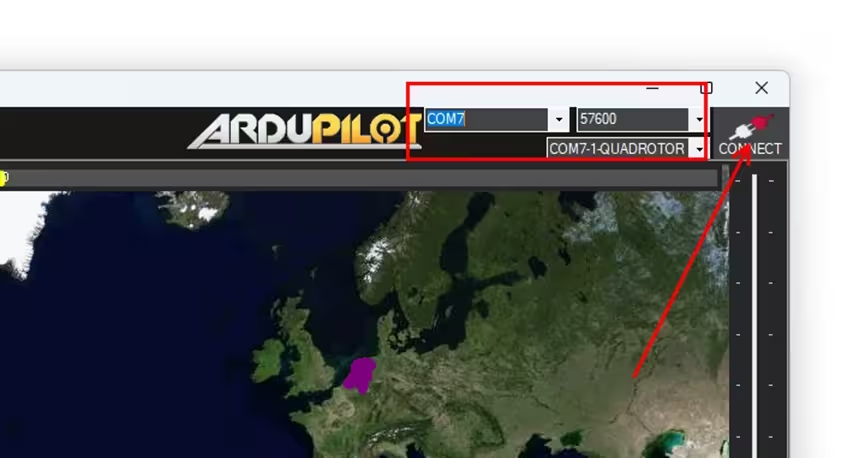
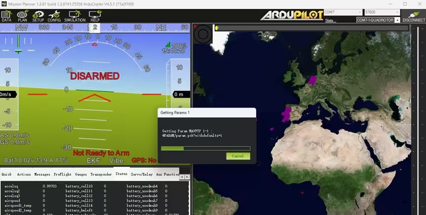
If all goes well it will connect, and the GCS will start reading the flight controller's parameters — usually finished within a few seconds.
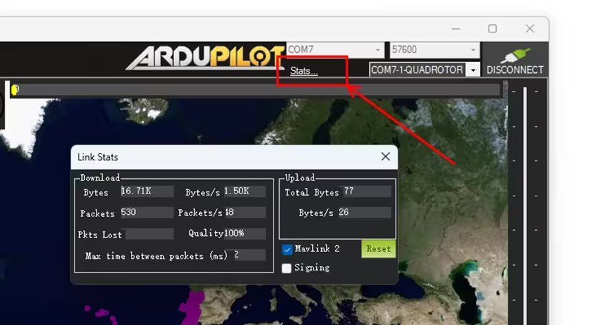
Once connected, click Link Stats in the top-right to see the downlink data rate (around 1–2 KB/s with default parameters) and link quality (packet-loss rate).
Troubleshooting
1. Slow link / high data latency
The attitude indicator reacts a few seconds after you move the flight controller.
This happens when the flight controller's downlink data volume exceeds the radio's throughput limit.
In its default mode, the LR900-F has a maximum uplink rate of 2.1 KB/s (downlink can reach 3.2 KB/s in FHSS mode). A typical flight controller running ArduPilot with Mission Planner's default settings sends about 1 KB/s downlink, which is within limits — but some flight controllers with three onboard IMUs send much more by default, which triggers this symptom.
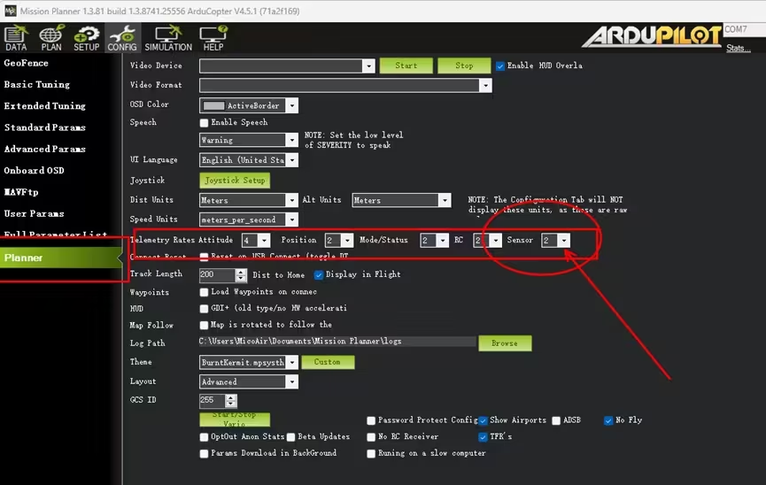
Fix it with one Mission Planner setting: on the CONFIG → Planner page, find the telemetry-rate options and change Sensor from its default value of 2 to 1.
There's also another case: if a MAVLink device is connected to another of the flight controller's serial ports and triggers MAVLink routing/forwarding, downlink volume can grow significantly. Disable forwarding on the serial port that the MAVLink device is on by setting SERIALx_OPTIONS = 1024 (Don't forward).
2. Low link quality in Mission Planner even at close range
See issue 1 — this is congestion / packet loss caused by data volume exceeding the link bandwidth, not a weak signal. Adjust the Mission Planner setting as in issue 1, or use MicoAir Assistant to set the radio to a higher rate mode. (For example, the LR24 ships in low-rate mode by default for longer range; try medium-rate mode.)
3. Stuck on "getting params"
Mission Planner receives flight-controller data and the attitude indicator moves, but it stays stuck loading parameters.
Two cases:
- If the parameter-loading progress bar doesn't move at all, there's a hardware problem on the line from the radio's Tx to the flight controller's Rx — check the wiring and the flight controller's pin header.
- If the progress bar moves but very slowly, it's still data congestion; see issue 1.
Translated and adapted into English by Robofusion from MicoAir's official tutorial. Original (Chinese): Ardupilot飞控-数传配置使用教程. Last updated upstream: 2025-12-30.