VIO vs Optical Flow — What's the Difference for Drones?
Both let a drone fly where there is no GPS, both point a camera at the ground, and both plug into the flight controller's EKF. That is where the similarity ends. Optical flow is a velocity sensor; visual-inertial odometry is a position sensor. This page explains what each one measures, why the difference matters in the air, and how to choose between the MicoVIO and the MTF optical flow sensors.
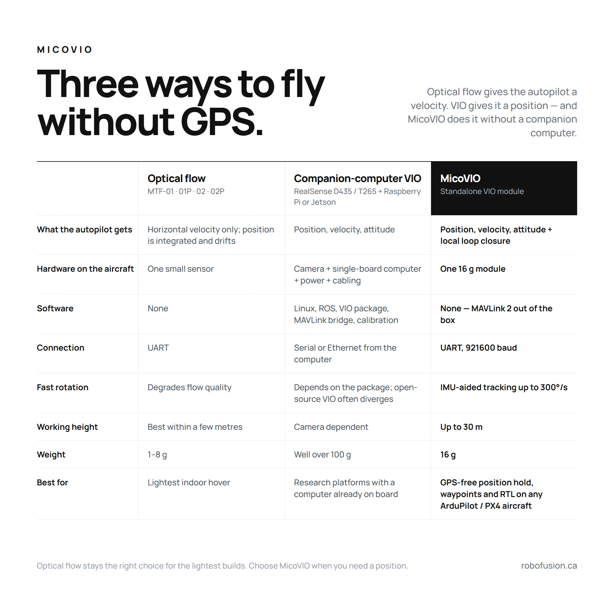
What optical flow measures
An optical flow sensor is a tiny, low-resolution camera looking straight down. Its chip compares one frame with the next and reports how fast the ground pattern moves across the image — in effect an angular rate, once the pixel motion has been scaled by the lens's focal length. On its own that rate is ambiguous: the same ground speed looks fast at 1 m and slow at 10 m. That is why every flow sensor carries, or needs, a rangefinder: horizontal velocity ≈ height × angular flow rate, after the flight controller has also removed the part of the image motion caused by the aircraft's own rotation (the sensor's gyro supplies that).
That velocity goes to the flight controller as an OPTICAL_FLOW message, and the EKF uses it to correct the velocity it already predicts from the IMU. Position is then integrated from velocity — and everything that is integrated accumulates error. Hold a flow-equipped drone perfectly still and its position estimate still creeps, because a small velocity bias, integrated for a minute, is a metre. Yaw the aircraft fast and the flow chip loses track altogether, because the ground sweeps across its field of view faster than it can match.
None of this makes optical flow bad. At 1–8 g and a fraction of the cost of any VIO system it gives a 3-inch quad a solid indoor hover, which is why the MTF-01, MTF-01P and MTF-02 / 02P are so popular. It simply is not a position sensor.
What VIO measures
Visual-inertial odometry tracks hundreds of distinct features — corners, edges, texture — across successive frames of a proper camera. From how those features move it solves for the camera's own motion in six degrees of freedom: three of position and three of orientation. The IMU does two jobs alongside: it predicts where the features should be in the next frame, so tracking survives fast rotation and brief blur, and it supplies the high-rate motion between the ~40 Hz camera updates. A rangefinder (the ToF on MicoVIO) fixes the metric scale, which a single camera cannot know by itself.
The output is a pose — position, velocity and attitude — sent as a MAVLink ODOMETRY message. The flight controller treats it as an external navigation source, exactly as it would a motion-capture system or a VOXL companion computer: position and velocity and yaw, not just velocity.
MicoVIO adds local loop closure. It keeps a short memory of recent images; when the current view matches one of them, the match becomes a position constraint that pulls the estimate back to where it was. In a hover this is the difference between an aircraft that sits on a tile and one that slowly tours the room.
Why VIO used to need a companion computer — and why MicoVIO doesn't
Until now, VIO on an open-source drone meant one of two stacks: a stereo camera (Intel RealSense D435 / D455) with a Raspberry Pi or Jetson running a VIO package under ROS, or the Intel RealSense T265 — which tracked on the camera itself but still needed a companion computer to bridge its pose into MAVLink. Either way: several hundred dollars, well over a hundred grams, days of integration, and in the first case a software stack that tends to diverge when the light changes or the aircraft is bumped. MicoVIO runs the entire pipeline on the module and presents itself to the flight controller like a GPS — one 4-pin UART cable, MAVLink 2, no companion computer. See the standalone section of the manual for the side-by-side.
Why error grows mainly with distance
Because VIO estimates position from what it sees, a stationary aircraft that keeps tracking accumulates very little error — the same features keep matching the same places. Error enters mostly as the aircraft moves over new ground, which is why VIO accuracy is quoted as a percentage of distance travelled (it can still drift or lose track in a bad scene, so "mainly with distance" is not "never with time"). MicoVIO's typical figure is 1 %; in MicoAir's outdoor tests against RTK, the RMS trajectory error over 136 m and 141 m flights was 0.73 m and 0.70 m — about 0.5 % of distance, a track-level statistic rather than an end-point error. An optical-flow position, by contrast, drifts whether you fly or not.
Side by side
| Optical flow (MTF-01 · MTF-01P · MTF-02 · MTF-02P) | MicoVIO (visual-inertial odometry) | |
|---|---|---|
| Sensor | Low-resolution flow chip + LED, laser or ToF rangefinder | Global-shutter HDR camera (120°) + IMU + ToF rangefinder |
| Measures | Ground motion across the image → horizontal velocity | Full 6-DoF motion: position, velocity, attitude |
| Position | Integrated from velocity by the EKF — drifts with time | Estimated directly; local loop closure holds a hover |
| Message to FC | OPTICAL_FLOW → EKF velocity aiding | ODOMETRY → EKF external navigation (position + velocity + yaw) |
| Trajectory / RTL | No usable trajectory; RTL needs GPS | ≈ 1 % typical trajectory error; GPS-free RTL possible where firmware supports it (not yet validated by us) |
| Fast rotation | Fast yaw and aggressive maneuvers degrade flow | IMU-aided tracking rated to 300°/s (manufacturer figure) |
| Working height | Best within a few metres of the ground | Up to 30 m |
| Light | > 60 lux (MTF-01) | > 1 lux |
| Processing | On the sensor | On the sensor — no companion computer |
| Weight | 1–8 g | 16 g |
| Firmware | ArduPilot, PX4, INAV, Betaflight | ArduPilot ≥ 4.5.2, PX4 |
Which one should you buy?
Choose optical flow when
- the job is "hover indoors without drifting into the wall" on a small aircraft, and nothing more;
- every gram counts — a tiny whoop or 2–3-inch micro (MTF-02 is 1 g);
- you fly INAV or Betaflight, which have no external-navigation input;
- the sensor budget is the main constraint.
Choose MicoVIO when
- you need a position, not just a damped hover: waypoints indoors, repeatable paths, scanning a warehouse aisle, flying under a bridge deck;
- you want return-to-launch with no GPS (with firmware that supports external-nav RTL);
- the aircraft yaws or flies aggressively — orbits, spins, FPV-style moves — and flow keeps dropping out;
- lighting is poor or changes hard (indoors to outdoors, bright sun on a reflective floor);
- you are building the kind of autonomous aircraft that until now needed a VOXL or a Jetson plus a stereo camera, and would rather carry 16 g on a spare UART.
Neither replaces GPS/RTK outdoors. VIO position is relative to take-off and grows ~1 % of distance in error; RTK is absolute to a few centimetres. Serious autonomous platforms fly RTK where there is sky and VIO where there is not — ArduPilot's EKF3 source switching makes exactly that hand-over possible.
Looking for an Intel RealSense T265 replacement?
For years the Intel RealSense T265 was the default way to give an ArduPilot or PX4 drone visual-inertial odometry. The camera did the tracking, a companion computer — Raspberry Pi, Jetson, Up Board — ran a bridge that turned its pose into MAVLink messages, and the autopilot consumed them; ArduPilot even gained a dedicated backend for it. Then Intel discontinued the T265, and the answers since have been either a ModalAI VOXL (a capable but full companion computer with a budget to match) or a stereo camera such as the RealSense D435 / D455 running open-source VIO — OpenVINS, VINS-Fusion — which puts you back in ROS, with the divergence problems that come with it.
MicoVIO fills that gap with less hardware than any of them. It does the tracking and the fusion on the module, adds a ToF rangefinder so scale and height are solved, and talks to the autopilot directly over a 4-pin UART as MAVLink 2 ODOMETRY. ArduPilot takes it through the external-navigation backend (VISO_TYPE 3, the ODOMETRY-message path), PX4 through EKF2 external vision (EKF2_EV_CTRL) — so if you ever set up a T265, the parameters will look familiar, minus the computer. Full parameter lists are in the MicoVIO manual.
How each one plugs into the flight controller
| Optical flow | MicoVIO | |
|---|---|---|
| ArduPilot | FLOW_TYPE 5, rangefinder as RNGFND1_TYPE 10, EKF EK3_SRC1_VELXY 5 (OpticalFlow) — see the Optical Flow Setup Guide | VISO_TYPE 3 on a MAVLink 2 serial port at 921600, rangefinder RNGFND1_TYPE 10, EKF EK3_SRC1_POSXY / VELXY / VELZ / YAW 6 (ExternalNav) — see the MicoVIO manual |
| PX4 | SENS_EN_PX4FLOW / flow via MAVLink, EKF2_OF_CTRL | MAVLink port in Onboard mode at 921600, EKF2_EV_CTRL 9, EKF2_HGT_REF 2 — see the MicoVIO manual |
| Board requirement | Any board with a spare UART, including F405 | Firmware with external-vision support — H7 boards; most F405 boards leave it out |
FAQ
What is visual-inertial odometry? Estimating a camera's motion by tracking visual features between frames and fusing that with an IMU. The output is a full 6-DoF pose relative to the starting point. On a drone it replaces GPS as the EKF's position source.
What does an optical flow sensor actually measure? How fast the ground pattern moves across a small downward camera — an angular rate, once scaled by the lens focal length. Multiplied by the height from a rangefinder (with the aircraft's own rotation removed) it becomes an approximate horizontal velocity. It is a velocity sensor; the flight controller integrates it to get position.
Why does optical flow drift and VIO drift much less? Integrating velocity integrates its errors, so a flow position wanders with time. VIO estimates position directly, predicts between frames with the IMU, and (on MicoVIO) closes local loops, so error grows mainly with distance flown — about 1 % typical under MicoAir's test conditions. That is not zero drift: lighting, texture and motion still matter, and tracking can be lost.
Can I use both on the same drone? You can, but VIO already supplies velocity, position and yaw, so the flow sensor adds little.
What replaced the Intel RealSense T265 for drone VIO?
After Intel discontinued the T265, the usual options were a ModalAI VOXL companion computer or a stereo camera such as the RealSense D435 running open-source VIO on a Raspberry Pi or Jetson under ROS. MicoVIO is the lighter answer: a 16-gram module that does the VIO itself and sends position, velocity and attitude to ArduPilot or PX4 as MAVLink 2 ODOMETRY over a UART — no companion computer.
Is VIO a replacement for GPS or RTK? Where there is no sky view, yes. For absolute outdoor accuracy, no — VIO is relative and its error grows with distance; RTK is absolute to centimetres.
Related
- MicoVIO — User Manual — including the manufacturer source, ArduPilot and PX4 references
- Optical Flow Setup Guide — ArduPilot / PX4 / INAV
- MTF-01 manual · MTF-01P manual · MTF-02 / 02P manual
- What Is RTK? · NxtPX4 V2 — the 20×20 PX4 board built for VIO research
Written and maintained by the Robofusion engineering team.