Optical Flow Setup Guide — ArduPilot / PX4 / INAV
One guide for the whole MTF family: the MTF-01, MTF-01P, and MTF-02 / MTF-02P all configure identically — wire the sensor to a spare UART, set the parameters below, and your drone hovers indoors without GPS.
Optical flow gives the EKF a velocity; position is integrated from it and drifts. If you need indoor waypoints, repeatable paths or GPS-free return-to-launch, look at the MicoVIO visual-inertial odometry sensor — and read VIO vs Optical Flow to see which one your build actually needs.
An optical flow sensor cannot stabilize an aircraft that doesn't already fly well. If you set every parameter perfectly but the airframe vibrates, you will get a drifting, twitching hover and blame the sensor. Verify vibration first (how, for each firmware), then add sensors. This single ordering mistake causes more "the sensor doesn't work" tickets than everything else combined.
How position hold actually works — and why vibration is the foundation

The flow sensor does not fly the aircraft. Read the diagram like any cascade control loop: the forward path runs along the top — position/velocity controller → attitude & rate controller → motors. Below it sit two nested feedback loops. The inner loop is the IMU: gyro and accelerometer sampled at kHz rates, feeding attitude and rate feedback straight back to the attitude controller, and simultaneously driving the EKF's high-rate motion prediction. The outer loop is where your new sensors live: the rangefinder supplies height — which is also what converts the flow camera's angular motion into real velocity in m/s (the same ground movement looks fast when low and slow when high) — and the optical flow velocity arrives at just 50–100 Hz as a correction to the EKF's IMU-based prediction. The corrected estimate closes the outer loop at the position controller.
Now trace the red dashed path from the motors block: the airframe's real motion is what the IMU is supposed to measure, but motor and prop vibration rides the exact same physical path into the IMU. A vibrating IMU means aliased gyro data and clipped accelerometers; the EKF's prediction wanders; and the slow 50–100 Hz flow corrections end up fighting a noisy estimate instead of trimming a clean one. The result is exactly what frustrated users describe: parameters all "correct", hover still breathing, drifting or oscillating. Both loops stand on the IMU — the sensor is the last 20%, the airframe is the first 80%.
Step 1 — prove the airframe flies clean
Hover the aircraft (GPS mode or manual, no flow yet) for 30–60 seconds and check the vibration data your firmware already records:
| Firmware | Where to look | Healthy |
|---|---|---|
| ArduPilot | Mission Planner status VibeX/Y/Z, or the VIBE message in dataflash logs | All axes < 30 m/s² sustained (occasional peaks OK); 30–60 is a gray zone; > 60 will cause problems. Clip0/1/2 counters must stay at (or very near) 0 — any steady climbing means the accelerometer is saturating |
| PX4 | Upload the log to Flight Review → Raw Acceleration plot | The z-axis trace must stay clearly separated from x/y in hover. If z overlaps x/y, vibration is too high — PX4's own rule of thumb |
| Betaflight / INAV | Blackbox log → spectral view in the log viewer | Gyro spectrogram shows distinct, narrow motor peaks over a low noise floor; a wall of broadband noise across the band means mechanical trouble |
If you fail these checks, put the flow sensor back in the drawer and fix the airframe:
- Props first — the cause in most cases. Damaged, warped or unbalanced props; even new cheap props benefit from balancing. Try a fresh set before anything else.
- Motors — worn bearings (spin by hand, feel for grinding), bent shafts after crashes, loose bells.
- Mounting — flight controller not torqued down, mushy double-sided tape instead of proper standoffs/grommets, or the opposite: hard-mounted FC on a frame that resonates. Cables pulling on the FC count too.
- Frame — cracked arms, loose arm bolts, resonant thin-plate arms; anything rattling (GPS mast, camera, VTX antenna).
Then let the firmware's filters clean up the rest
Filters treat residual noise, not mechanical faults — apply them after the checklist above:
- ArduPilot: enable the harmonic notch (
INS_HNTCH_ENABLE = 1), driven by throttle, ESC RPM (with bi-directional DShot), or the in-flight FFT (INS_HNTCH_MODE). Log the spectrum withINS_LOG_BAT_MASK = 1to see before/after. - Betaflight: turn on the RPM filter (requires bidirectional DShot) — the single biggest noise win — plus the default dynamic notch.
- INAV: enable the dynamic gyro notch; keep the gyro LPF at sane defaults rather than chasing latency.
- PX4: use the ESC-RPM dynamic notches (
IMU_GYRO_DNF_EN) or configure the software notch/LPF (IMU_GYRO_NF0_FRQ,IMU_GYRO_CUTOFF) at the prop frequency seen in Flight Review's FFT.
Step 2 — protocol matching (now automatic)
Current-production MTF sensors auto-detect your flight controller's firmware on power-up and switch to the matching protocol themselves — ArduPilot, PX4, INAV or Micolink. Wire it, power it, done; there is no longer any need to pick a firmware variant when ordering.
Manual override still exists for older units or special cases:
| Firmware | Sensor protocol |
|---|---|
| ArduPilot | mav_apm |
| PX4 | mav_px4 |
| INAV | msp |
| FMT / custom code | Micolink (protocol reference) |
Set it in MicoAssistant, the browser-based configuration tool, or on the MTF-02P via solder pads (pads take priority over software).
Pre-auto-detection sensors must match manually — "distance shows up but no optical flow" on an old unit is almost always a protocol mismatch (e.g. an mav_px4 sensor on an ArduPilot board).
Step 3 — firmware parameters
ArduPilot (≥ 4.2.0)
Serial and sensor parameters — n is the UART you wired (e.g. SERIAL5):
SERIALn_PROTOCOL = 1      # MAVLink1
SERIALn_BAUD     = 115
SERIALn_OPTIONS  = 1024   # Don't forward — 4.6 and earlier; see the 4.7 note below
FLOW_TYPE        = 5      # MAVLink optical flow
RNGFND1_TYPE     = 10     # MAVLink rangefinder
Reboot (or refresh parameters), then:
RNGFND1_MIN      = 0.01   # metres (ArduPilot 4.7 and later)
RNGFND1_ORIENT   = 25     # facing down
RNGFND1_MAX      = 8      # MTF-01 — use your sensor's real range in metres:
                          # 12 (MTF-01P) / 6 (MTF-02P) / 2.5 (MTF-02)
- Rangefinder distances are now in metres.
RNGFND1_MIN_CM/RNGFND1_MAX_CMbecameRNGFND1_MIN/RNGFND1_MAX. On 4.6 and earlier use the old names in centimetres:RNGFND1_MIN_CM = 1,RNGFND1_MAX_CM = 800(MTF-01), 1200 (MTF-01P), 600 (MTF-02P) or 250 (MTF-02). Typing 800 into the newRNGFND1_MAXwould mean 800 m. - "Don't forward" moved in ArduPilot 4.7: it is no longer
SERIALn_OPTIONS = 1024(bit 10) but bit 1 ofMAVn_OPTIONS(value 2).MAVncounts MAVLink ports in order: USB (SERIAL0) isMAV1, the next serial port set to a MAVLink protocol isMAV2, and so on. Upgrading a board from 4.6 carries the setting over automatically; it only matters when you type values from an older guide.
EKF source — flow-only indoor flight
This is the part most guides skip. Telling the EKF to trust flow velocity instead of GPS:
AHRS_EKF_TYPE    = 3
EK3_SRC_OPTIONS  = 0
EK3_SRC1_POSXY   = 0      # no absolute XY position source
EK3_SRC1_POSZ    = 2      # height from rangefinder
EK3_SRC1_VELXY   = 5      # XY velocity from optical flow
EK3_SRC1_VELZ    = 0
EK3_SRC1_YAW     = 1      # compass
EKF source — GPS outdoors, flow indoors (advanced)
Keep GPS as source 1 and configure flow as source 2, switched from the radio. Not recommended as a first setup:
EK3_SRC2_POSXY   = 0
EK3_SRC2_POSZ    = 2
EK3_SRC2_VELXY   = 5
EK3_SRC2_VELZ    = 0
EK3_SRC2_YAW     = 1
RC6_OPTION       = 90     # RC6 3-position switch selects EKF source;
                          # middle position = source 2 (optical flow)
First confirm firmware ≥ 4.2.0. If the version is fine, your board's firmware was built without optical flow support — common on F405-class boards where flash constraints force feature cuts. Use ArduPilot's custom firmware builder to build with flow enabled, or use a board with more flash such as the H743 V2.
PX4
Sensor protocol: mav_px4. Parameters differ by firmware line:
1.12.x – 1.13.x
MAV_1_CONFIG   = TELEM n     # reboot after setting
MAV_1_MODE     = Normal
SER_TELn_BAUD  = 115200 8N1
SENS_FLOW_ROT  = No rotation
EKF2_AID_MASK  = use optical flow
EKF2_RNG_AID   = Range aid enable
EKF2_HGT_MODE  = Range sensor
1.14.x – 1.16.x
MAV_1_CONFIG   = TELEM n     # reboot after setting
MAV_1_MODE     = Normal
SER_TELn_BAUD  = 115200 8N1
EKF2_OF_CTRL   = Enabled
EKF2_RNG_CTRL  = Enabled
EKF2_HGT_REF   = Range sensor
Reboot again; SENS_FLOW_ROT only appears in QGC after the flow sensor has been detected once (its default "No rotation" is already correct).
1.17.x and later — additionally set MAV_PROTO_VER = 1.
INAV
Sensor protocol: msp. Enable the optical flow and rangefinder sensors in the INAV configurator. Avoid INAV 7.1.1 — a known bug breaks this sensor family; use a newer (or older) release.
Step 4 — tune altitude hold first, then position hold
Resist the urge to enable everything and launch. Split the bring-up so a failure points at one subsystem, not two coupled ones:
- Altitude hold first. Indoors or over a sensor-friendly surface (matte, textured, decent light), configure only the rangefinder as the height source and fly altitude-hold. The aircraft should lock its height crisply near the ground with no stair-stepping or slow porpoising. If height is unstable, fix that now — range data, surface, or vibration — before flow ever enters the picture.
- Then add optical flow as the velocity source and tune position hold in the same friendly environment. Any new misbehavior is now attributable to the flow side (light, texture, orientation, scale) instead of an ambiguous mix.
This is how we bring up every test aircraft in-house — it turns "it drifts and I don't know why" into two short, answerable questions.
Verify before you fly
Connect over USB (not telemetry — see below) and open QGC's MAVLink Inspector (or Mission Planner's equivalent). You should see both DISTANCE_SENSOR and OPTICAL_FLOW_RAD messages arriving:
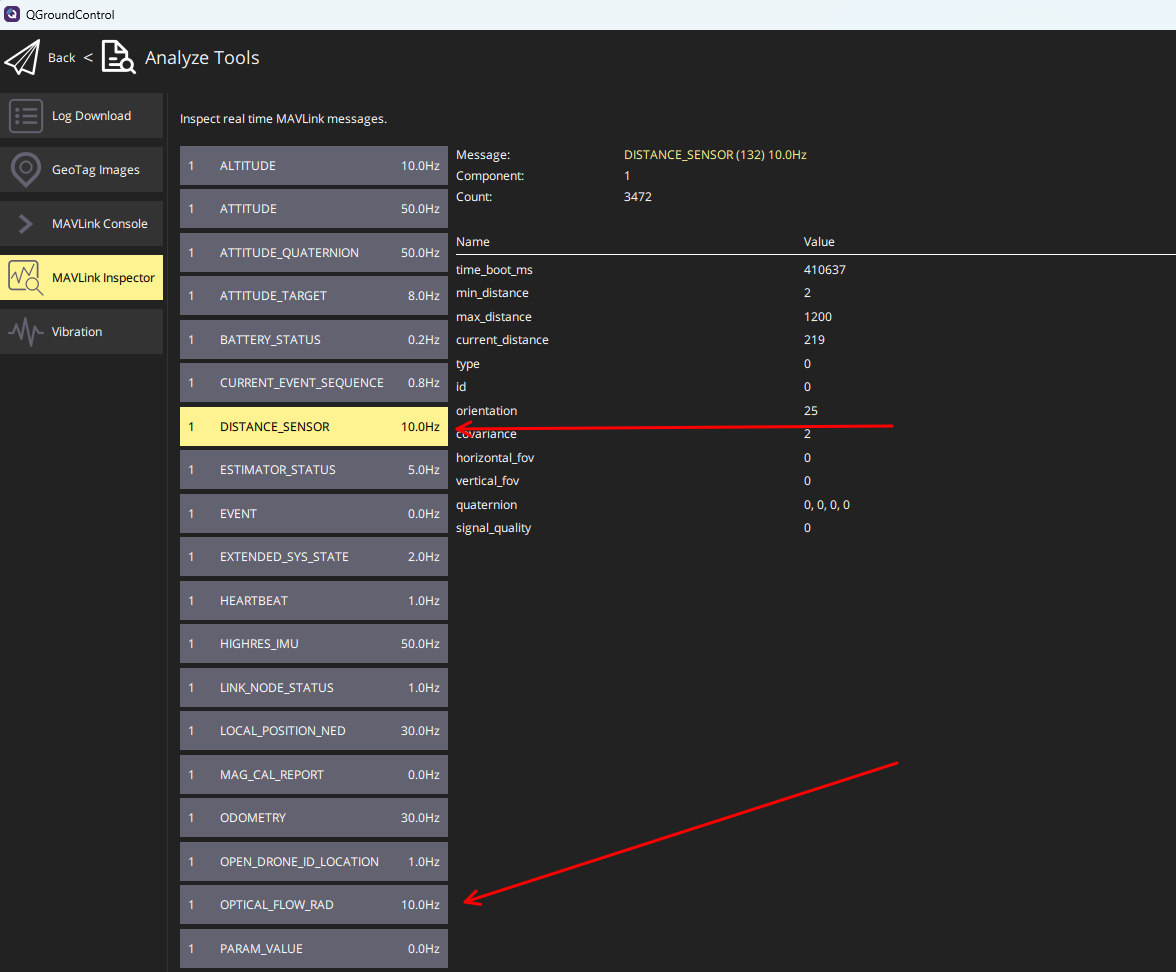
Message rates shown in the GCS are set by the flight controller's link bandwidth, not by the sensor — don't expect to see 100 Hz there, and don't worry about it.
Troubleshooting
Distance data but no optical flow
Two usual causes: a protocol mismatch (older, non-auto-detect units — see Step 2), or you're connected via a telemetry radio — on a slow link PX4 selectively drops messages, so OPTICAL_FLOW_RAD may simply not be forwarded to the GCS. Check over USB before suspecting the sensor.
PX4 keeps resetting my position estimate to zero
Normal. Optical flow provides velocity only, no absolute position, so while disarmed PX4 periodically re-zeros the estimated position to bound drift.
The rangefinder reads far less than the rated range
The rating is a laboratory number: measured against a 90%-reflectivity target (think bright white board) at a stated ambient light level — the spec table lists both a 600 lux (indoor) and a 70 klux (direct summer sun) figure, and they differ for a reason. Outdoors at noon, sunlight floods the receiver with infrared; over a low-reflectivity surface the return signal shrinks again — dry grass reflects only a fraction of what a white wall does, and dark asphalt can be under ~10%. Practical expectations: bright concrete at noon sits between the two rated figures; grass or dark ground in strong sun can halve the sunlit rating. This is physics, not a defective unit — and it is exactly why the laser-based MTF-01P holds 8 m even at 70 klux while LED units derate more steeply.
Position hold is mushy or drifts
Check the basics the physics demands: ground texture (bare uniform floors are hard to track), light (>60 lux), altitude within the rangefinder's real range, and the sensor lens clean and unobstructed. A printed case keeps fingers and crashes off the optics.
Related guides
- MTF-01 · MTF-01P · MTF-02 / MTF-02P
- Free 3D-printable cases & mounts
- ArduPilot — Telemetry Setup Guide
Where to buy
The sensors this guide configures, shipped from Canada with free Canada-wide shipping:
- MicoAir MTF-01 — 8 m range, the 5–7 inch all-rounder
- MicoAir MTF-01P — 12 m laser, outdoor-capable
- MicoAir MTF-02P — 1.5 g micro sensor, outdoor-capable
Written and maintained by the Robofusion engineering team.